Atomic force microscopy for studying surface topology.

Ever wonder what a surface looks like at the microscale? Atomic force microscopy is commonly used in materials science to visualize surface topology. While it is often considered to be quite slow, it is often a useful materials characterization technique.
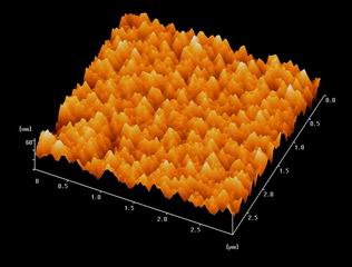
Image credit - An image of the surface of ZnO using AFM.
Atomic force microscopy measures the interaction between a tip affixed on a cantilever and a sample’s surface. The cantilever acts as a spring with a known force constant, and a laser reflected off of the cantilever onto a detector is used to measure the cantilever deflection. As the tip is scanned across the sample in a raster pattern, the deflection at each position is saved and compiled into a map. Typically, a mirror is used to lengthen the laser path and allow for a higher sensitivity of deflection detection. Using the force constant and cantilever deflection, the atomic force repulsion between the sample and tip may be calculated with Hooke’s law ($F = -kx$).
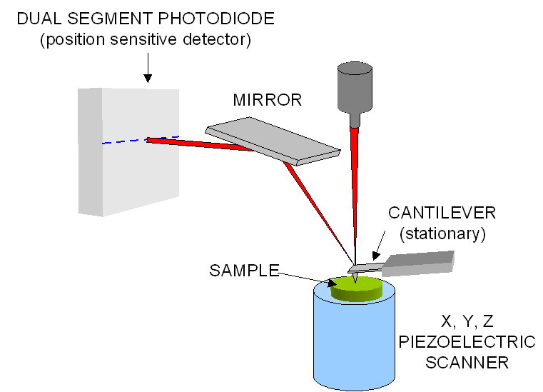
Atomic force microscopy operates by scanning the sample with a physical probe and thus allows for true measurements of surface heights, as opposed to a scanning electron microscope which is only capable of producing two-dimensional images. A feedback loop is used to maintain a constant sample-tip interaction force. The changes necessary to maintain a constant force and then used to generate a topological map of the surface. For example, in the schematic above the sample is placed on a stage which can move up and down normal to the cantilever tip. When scanning across a localized peak on the material, the stage will need to move away from the cantilever in order to maintain a constant force interaction. Likewise, when scanning across a localized valley, the stage will need to be brought closer to the cantilever. It is this movement which is recorded and used to generate a topological map.
The two most common AFM modes are contact and tapping, which describes the action of the tip as the sample is being scanned. Contact mode involves maintaining a constant contact force with the sample. The piezoelectric actuator adjusts the cantilever height in order to respond to changes in surface height on the sample. For the tapping mode, the piezoelectric actuator oscillates the cantilever near its resonant frequency. The feedback loop for tapping mode involves either the oscillation of amplitude or frequency. Tapping allows for scanning with extremely low friction because adhesion is a time-dependent process. Simply, the tip does not remain in contact with the material for enough time to adhere, which allows for the scanning of viscous samples with little trouble. Another benefit to tapping is the ability to measure the phase lag. This lag associated with the cantilever oscillation can be caused by changes in material properties, such as adhesion, elasticity, or viscoelasticity, and is utilized for phase imaging. Tapping is generally the preferred method for AFM due to its near frictionless interaction with the material and the additional phase lag information that can be captured.
Atomic force microscopy proves advantageous over other microscopy techniques when an accurate surface height measurement is required. The true surface height can be obtained by AFM because the probe is physically interacting with the sample, and using an extremely fine tip that provides us with sub-Angstrom resolution. This is a much higher resolution than optical microscopy, which is diffraction limited to around 250 nm resolution. While scanning electron microscopy can be used for even higher resolutions than AFM, it generates a two-dimensional image; accurate surface height measurements are more easily obtained through atomic force microscopy.
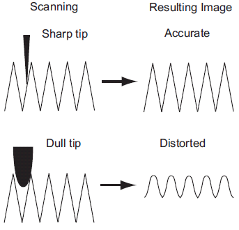
The images produced by AFM are limited by the nature of the tip. If a surface protrusion is narrower than the tip, the image displayed will simply be an image of the tip. Moreover, if a surface cavity is more narrow than the tip, the tip will not be able to enter and thus will not display the cavity. An ideal AFM tip would be narrower than any asperity on the surface, giving a near-true image of the material topography. Tips may be characterized by scanning over a reference sample that has many small, sharp protrusions. The repeated image displayed at each asperity represents the shape of the tip. If a probe has more than one tip, this is apparent in the image.