What is x-ray diffraction?

X-ray diffraction is a common materials characterization technique that allows for identification of crystal orientations and interatomic spacing. X-rays are used for this because the wavelength is on the same length scale as interatomic spacing and lattice parameter values.
What's going on?
An x-ray is generated in a vacuum tube by heating up a tungsten filament past its work function to eject electrons. Vacuum conditions are necessary in order to increase the electron mean free path. The electrons are accelerated into a copper cathode with an energy on the order of 25 keV. Electron collisions with the copper cathode result in inner shell ionizations, producing x-rays as higher-energy electrons drop to fill the lower-energy vacancy. Electrons from various higher energy levels drop, producing electromagnetic waves of varying energy. Thus, x-rays of multiple wavelengths (of type K-beta and K-alpha) are generated . For x-ray diffraction, it is ideal to have monochromatic light interacting with the sample, so the K-beta x-rays are filtered out with a nickel plate. Although there are indeed two associated K-alpha energies, the energies are so similar that it does not significantly affect the overall peak profile. The x-rays pass through a collimator to adjust the beam width.
A little background with Bragg's law
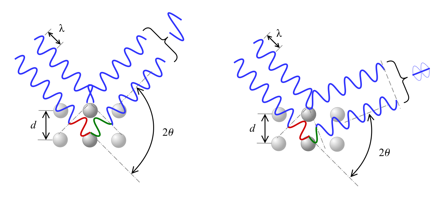
Bragg’s Law describes the relationship for constructive interference, where x-rays of wavelength λ incident on the material at angle θ are diffracted by crystal planes separated by distance d and n represents an integer.
[n\lambda = 2d\sin (\theta )]
As shown see below, a phase shift in the wave causes either constructive inference, as shown on the left, or destructive interference, depicted on the right, according to the 2θ angle.
Equations for interpreting XRD results
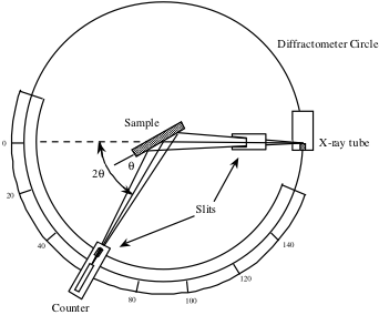
The counter, seen below in a schematic of an x-ray diffractometer, is rotated over a range of 2θ values and records the x-ray signal intensity reflected from the crystal at each position. This intensity measured as a function of 2θ is used to generate a peak profile.
For angles that satisfy the Bragg condition, a peak in x-ray signal will be observed due to the constructive interference. These peaks are then used to identify crystal directions and calculate lattice parameters. For cubic systems, the interplanar spacing, d, may be calculated by the following equation derived from the crystal geometry, where a is the lattice parameter and h, k, and l are the Miller indices.
[{d_{hkl}} = \frac{a}{{\sqrt {{h^2} + {k^2} + {l^2}} }}]
Combining Bragg's law and the interplanar spacing yields the following equation.
[\frac{{{\lambda ^2}}}{{4{a^2}}} = \frac{{{{\sin }^2}({\theta _{hkl}})}}{{{h^2} + {k^2} + {l^2}}}]
Here, we've moved all of the constants to the left side of the equation, allowing us to compare ratios of sin2(θ) values and Miller indices between different peaks.
When the incident electromagnetic wave impinges on the sample material, electrons residing with the material are perturbed into an oscillating pattern, which generates new x-rays and effectively scatters the incident light waves. Two types of scattering occur: coherent or elastic scattering involves tightly-bound oscillating electrons that scatter x-rays of the same wavelength, and incoherent scattering which occurs when loosely-bound electrons are set into oscillatory motion and generate x-rays of different energy. X-ray diffraction measures the intensity of coherently scattered x-rays, which peaks where waves constructively interfere. The atomic scattering factor may be defined as a ratio of the amplitude of the wave scattered by an atom divided by the amplitude of the wave scattered by a single electron. This ratio essentially describes the scattering efficiency of an atom for a given direction.
Example of XRD data
Here's the data collected from an experiment I did during my undergraduate lab course trying to identify an unknown metal based on its crystal structure.
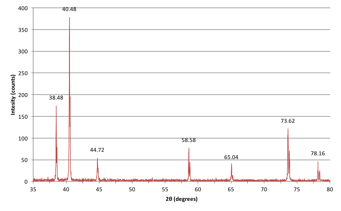
How do I interpret these peaks?
| Crystal Structure | Conditions |
|---|---|
| Simple Cubic | all h, k, l values |
| Body Centered Cubic | h+k+l must be even |
| Face Centered Cubic | h, k, and l must be all odd or all even |
Structure factors account for instances where a plane may exist halfway between two neighboring planes and causes destructive interference to occur. These factors result in a set of rules for different crystal structure geometries which determine when constructive interference may occur. The table above lists the Miller index parameters in which constructive interference will occur. A more extensive table is shown below. By comparing ratios of sin2θ (denoted as $Q^2$ in the second table) for different diffraction peaks, the crystal structure and Miller indices may be determined.
| Crystal Plane (hkl) | $Q^2$ | Space lattices from which reflections are possible | |||
|---|---|---|---|---|---|
| 100 | 1 | SC | |||
| 110 | 2 | SC | BCC | ||
| 111 | 3 | SC | FCC | DC | |
| 200 | 4 | SC | BCC | FCC | |
| 210 | 5 | SC | |||
| 211 | 6 | SC | BCC | ||
| – | 7 | ||||
| 220 | 8 | SC | BCC | FCC | DC |
| 300, 221 | 9 | SC | |||
| 310 | 10 | SC | BCC | ||
| 311 | 11 | SC | FCC | DC | |
| 222 | 12 | SC | BCC | FCC | |
| 320 | 13 | SC | |||
| 321 | 14 | SC | BCC | ||
| – | 15 | ||||
| 400 | 16 | SC | BCC | FCC | DC |
X-ray diffraction has a wide range of applications for materials characterization. It may be used as an experimental method to experimentally determine the volume of a unit cell for theoretical density calculations. Additionally, if the material is under residual stress the distorted lattice will exhibit a range of d-spacings that satisfy Bragg’s law, resulting in much wider diffraction peaks. The diffraction peak width may also be used in determining particle size.